The reticle view
Goal of this article: see the solution as a sight picture — your own reticle with the trajectory mapped onto it — and use the three overlays it can draw.
The other two views tell you what to hold. This one shows you where in the reticle that hold lands,
which is what you are actually doing behind the rifle. Reach it with Ctrl+R or
View → Show → Reticle.
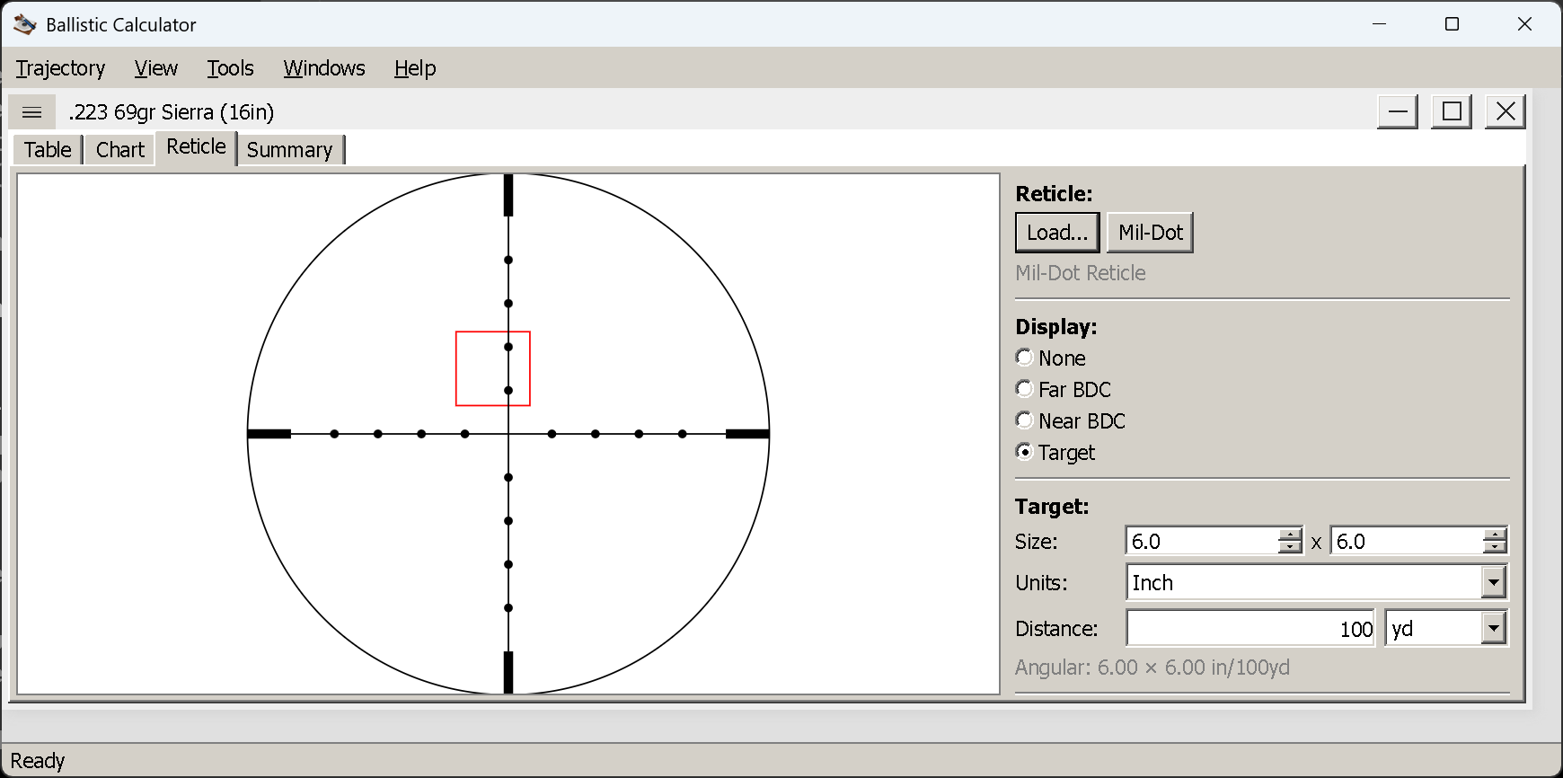
A Mil-Dot reticle with the Target overlay: a 6 × 6 in target at 100 yd, drawn to scale, with its angular size printed underneath.
Choosing a reticle
The view starts empty — the name reads (none) and there is nothing to draw on.
Mil-Dotdraws a standard mil-dot reticle in one click — 12 × 12 mrad, dots at whole milliradians, as a mil-dot reticle’s should be. It is built in, so there is no file to find.Load…opens thedata/reticlefolder, which ships with 34 — listed below. Your own reticles, built in the separate Reticle Editor application, live here too.
The shipped reticles
They fall into two kinds, and the distinction decides how far a mark can be trusted.
Measuring grids (13)
Marks on whole grid units — places on a ruler, so they are correct for any load, and the application
supplies the ranges. GERMAN4 and the M16 picture carry no marks at all; they are sight pictures.
| Reticle | What it is |
|---|---|
GERMAN4 |
German #4 hunting picture |
H58 |
H58-style grid with a christmas tree |
LEUP-CCH |
Leupold FFP CCH (Mark 5HD) — mrad grid with a 20-row christmas tree |
LEUP-CMR-MIL |
Leupold CMR-MIL Illum. FFP (Mark 4HD 2-10×) — mrad tree, 5 rows |
M-16 Iron 3 Inch Eye Relief |
M16 aperture and post |
MILDOT |
Mil-Dot, in true milliradians |
MOA-GRID |
MOA crosshair, 1 MOA hashes to ±14 — MILDOT’s field of view |
VUDU-LE5 |
EOTech Vudu LE-5 (FFP) — mrad christmas tree, cross-hair in the speed ring |
VUDU-MD1 |
EOTech Vudu MD1 (FFP) — plain mrad crosshair, 0.5 mrad graduation |
VUDU-MD2 |
EOTech Vudu MD2 (FFP) — plain MOA crosshair, 1 MOA graduation to ±30 |
VUDU-SR1 |
EOTech Vudu SR-1 (FFP) — mrad crosshair; speed ring out of scope |
VUDU-SR4 |
EOTech Vudu SR-4 (FFP) — MOA duplex ladder to 40, with speed ring |
VUDU-SR5 |
EOTech Vudu SR-5 (FFP) — mrad christmas tree, dot in the speed ring |
Load-calibrated ladders (21)
Marks etched at one load’s drops. They mean what they say for that load and something else for anything else — which the application will tell you, because it labels each mark from your trajectory rather than from the etching.
| Reticle | What it is |
|---|---|
ACOG-TA31 |
Trijicon TA31 (ACOG 4×32), 5.56 chevron |
ACOG-TA31-762mm |
Trijicon ACOG 4×32, .308 amber crosshair (TA01NSN-308) |
ACOG-TA44-556mm |
Trijicon ACOG 1.5×16S, RTR .223 |
ACOG-TA44-9mm |
Trijicon ACOG 1.5×16S, RTR 9 mm PCC |
ACOG-TA648 |
Trijicon TA648, .50 BMG |
HURON-BDC-HUNTER-4 |
Trijicon Huron 1-4×24 BDC Hunter Holds (SFP, at 4×) |
HURON-BDC-HUNTER-6 |
Trijicon Huron 1-6×24 BDC Hunter Holds (SFP, at 6×) |
HURON-BDC-HUNTER-9 |
Trijicon Huron 3-9×40 BDC Hunter Holds (SFP, at 9×) |
LEUP-CMR-W556 |
Leupold CMR-W 5.56 Illum. FFP (to the 20 mil mark) |
LEUP-CMR-W762 |
Leupold CMR-W 7.62 Illum. FFP (to the 20 mil mark) |
LEUP-CMR2 |
Leupold Illum. CM-R² (SFP, at 6×) |
PSO-1 |
PSO-1 (SVD), in Soviet thousandths |
SPECTER-5.56 |
Elcan Specter 1-4×, 5.56 |
SPECTER-7.62 |
Elcan Specter DR 1-4×, 7.62 (at 4×) |
VCOG-16-556-55gr |
Trijicon VCOG 1-6×24, 5.56 segmented BDC (at 6×) |
VCOG-16-762-175gr |
Trijicon VCOG 1-6×24, 7.62 segmented BDC (at 6×) |
VCOG16-300BLK |
Trijicon V-COG 1-6×24, 300 BLK (at 6×) |
VUDU-BD1 |
EOTech Vudu X BD1 (SFP) |
VUDU-HC3 |
EOTech Vudu HC3 (SFP, at 8×) |
VUDU-SR2 |
EOTech Vudu SR-2, 7.62 (FFP) |
VUDU-SR3 |
EOTech Vudu SR-3, 5.56 (FFP) |
Several are second focal plane, marked SFP above with the magnification they are true at — the three
Hurons, the CM-R², VUDU-BD1 and VUDU-HC3. Their subtensions hold at that setting and nowhere else — see
focal planes below.
Every shipped reticle is documented
The data/reticle folder is not just files — it carries its own documentation, which ships with the
application and is readable in any text editor or on the repository:
data/reticle/README.mdis the index. Two tables, one per kind, and for every load-calibrated reticle the full set of inputs: ammunition, muzzle velocity, sight height, zero, the ranges its marks stand for, and which library entry to load so the labels land on the etched ranges. Both tables are kept sorted by name.- A companion
.mdbeside every.reticle—SPECTER-7.62.md,VUDU-SR4.md,PSO-1.mdand so on. Each gives the pattern element by element, a mark-by-mark table with subtensions, the ranging features and the target size they assume, how the load was identified where it was fitted rather than published, and — importantly — what was left out and why.
That last point is worth the detour if a reticle ever looks wrong. Several files deliberately omit part of
the real etching: the CMR-W wind trees, because no source publishes their positions; VUDU-SR1’s speed
ring, undimensioned in its manual; the field-stop posts on several files, cropped so the drop ladder is not
dwarfed. Each omission is stated in that reticle’s own .md, so a missing feature can be told apart from a
mistake.
Focal planes, and what the drawing cannot know
The name of the loaded reticle is shown under the buttons, and the reticle stays loaded while you change overlays.
One assumption to be aware of: the picture is drawn at the reticle’s own subtension, as its definition states it. For a first focal plane scope that is true at any magnification. For a second focal plane scope the reticle only subtends its nominal values at one magnification — usually maximum — so the sight picture here corresponds to that setting and not to whatever you happen to be dialled to.
The three overlays
The Display radio buttons choose what is drawn with the reticle. They are exclusive: one at a time.
None
The reticle alone. Useful for checking a reticle you have just built, or for seeing the bare subtensions.
Far BDC
Blue distance labels at the points past your zero, each sitting at the elevation where that range’s
hold falls in the reticle. This turns your reticle into a bullet-drop compensator for this load: the
labels say which mark is 400 yd, which is 500 yd, and so on. Each label carries its unit — 552yd or
505m — so a printed sight picture cannot be misread as the other system; the unit follows the window’s
measurement system, like everything else on the tab.
Near BDC
The same labelling for the stretch before the zero, where the bullet is still climbing to the sight line. This is the part shooters usually forget: with a 300 yd zero, a 100 yd target is not on the crosshair either, and the near marks tell you by how much.
Where Near stops and Far starts
Split at, under the radio buttons, is the distance that divides the two. It starts at your zero
— the natural place, since that is where the bullet crosses the sight line — and it follows the zero as
you change the shot, in the window’s own unit.
It is editable because the zero is the wrong split for some loads. A .22 LR zeroed at 50 yd, or a subsonic load, puts almost everything worth labelling on one side of it: Far is then a crowd of marks and Near is nearly empty, or the reverse. Setting the split where the marks actually thin out gives you two readable overlays instead of one useless one.
Two details worth knowing:
- Once you type a split of your own, it stays yours. Editing the shot afterwards will not quietly put it back to the new zero. Clear the field to go back to following the zero.
- The box is enabled only while Far BDC or Near BDC is selected; it changes nothing in the other two modes.
Both BDC overlays are computed from a fine trajectory — 2.5 m steps, out to at least 3,000 m (or your
Maximum Distance if you set it further) — independently of the Step you set for the table. Making the
table coarser will not coarsen the marks. Loads that run out of speed sooner stop where the bullet stops:
the engine ends a run below 50 ft/s or past 10,000 ft of drop, so marks simply cease past that point.
Target
Draws a target box to scale, at a distance, behind the reticle lines, so it reads like a real sight picture rather than a diagram.
| Control | Notes |
|---|---|
| Size | Width × height of the target |
| Units | Inch or Centimeter — this is its own choice, independent of the window’s measurement system |
| Distance | In the window’s unit: yd or m |
| Offset H / V | Optional. Moves the box away from the hold, in the window’s angular unit — positive is right and up. Empty means none |
Underneath, the panel reports the target’s angular size in your chosen angular unit — for example
Angular: 6.00 × 6.00 in/100yd. That figure is the whole point of the overlay: it tells you whether the
target is big enough to hold on, and it is the number that decides whether a reticle’s marks are fine
enough for the shot you are planning.
Trying a rangefinder out
The box normally sits on the hold — where the bullet lands at that distance — which is what you want
for judging whether a target fits between the marks. Offset H and Offset V let you put it somewhere
else, and the reason they exist is the ranging scales several reticles carry: the stadia at the lower
left of the Elcan Specters, the Vudu speed rings, the PSO-1’s rangefinder curve. Until now there was no
way to hold a target against one of them and see whether it read true.
The method is the same as behind the rifle:
- Load the reticle and pick Target.
- Set Size to whatever the scale assumes — each reticle’s
.mdsays. The Specters assume 76 cm (30 in); the PSO-1 assumes a 1.7 m standing figure. - Offset the box onto the scale. Both values are usually negative, because ranging features sit low and
left: on
SPECTER-7.62the scale is around −25 MOA horizontally and −65 MOA vertically. - Now change Distance. The box shrinks as the range grows, and the distance at which it just fits a given bar is what that bar means.
If the reticle is honest and your target size matches its assumption, the fit lands on the bar’s own labelled range. That is worth doing once on a reticle you intend to range with — it is also the quickest way to catch a reticle whose ranging scale was drawn rather than computed.
The offsets apply to the moving-target box as well, so the dashed aim-off mark travels with the target rather than being left behind at the hold.
Moving targets
Tick Moving target inside the Target overlay and two more fields appear: the target’s Direction, set by number or by dragging the dial, and its Speed in mph or km/h.
The panel then reports the lead as text — Lead: 1.25 mil left, say — and draws a dashed box at the
aim-off position, offset from the static target by that lead. Aiming at the dashed box is the hold.
The lead is computed from the time of flight to that distance and the target’s crossing component, so a target moving straight toward you needs none, and a target crossing at right angles needs all of it. The direction convention matches the wind dial’s: the readout says left or right explicitly, so there is no sign to interpret.
Building your own reticle
The Reticle Editor is a separate application in the same folder (ReticleEditor.exe on Windows,
ReticleEditor on Linux). It works in the reticle’s own angular coordinate space and builds a reticle out
of lines, paths, circles, rectangles, text and BDC marks. Anything it saves into data/reticle appears in
this view’s Load… dialog.
It has four articles of its own: what it is for, size and zero, elements and paths.
Things worth knowing
- No reticle, no picture. The overlays need a reticle to draw on; load one first.
- The overlays need a solution. They are drawn from the current trajectory, so they follow every change you make in the Shot Parameters dialog.
- The angular unit follows
View → Angular Units. The target’s angular size and the lead readout are both expressed in it — a reticle marked in mils is easiest to read with mils selected. - A second-focal-plane scope is only true at one magnification. See above; the drawing cannot know what you have dialled.
Next
Comparing loads — putting two solutions on one chart and reading the difference.
(The summary view, the fourth of the four, is still to be written.)